Technical
Q&A
We Have Answers
Smart-Hose® Technologies is committed to providing our distributors and end-users with the best information possible regarding the usage of our products and general safety practices. If you have a subject that is not covered in this section, please send us a message (link to form.)
We look forward to answering your questions!
Working Pressure:
The force applied to an object perpendicular to the surface.
(Trying to break through the walls of the hose.)
Measured as pounds per square inch/PSI.
End Force:
The force that travels longitudinally along the hose assembly.
(Trying to push the fitting out of the hose.)
End Force = Area x Pressure
Note: End force is an important factor for hoses that are 2″ and larger in diameter. End force becomes greater as the diameter and pressure increase. See chart below…
END FORCE CHART
| Hose ID | 50 PSI | 100 PSI | 200 PSI | 300 PSI | 500 PSI | 1000 PSI |
|---|---|---|---|---|---|---|
| 1/4" | 2 | 5 | 10 | 15 | 25 | 49 |
| 1/2" | 10 | 20 | 39 | 59 | 98 | 196 |
| 1" | 39 | 79 | 157 | 236 | 393 | 785 |
| 2" | 157 | 314 | 628 | 942 | 1571 | 3142 |
| 3" | 353 | 707 | 1414 | 2121 | 3534 | 7069 |
| 4" | 628 | 1257 | 2513 | 3770 | 6283 | 12566 |
| 5" | 982 | 1964 | 3927 | 5891 | 9818 | 19635 |
| 6" | 1414 | 2827 | 5655 | 8482 | 14137 | 28274 |
| 8" | 2513 | 5027 | 10053 | 15080 | 25133 | 50266 |
Using water as an example: In the event of a complete hose failure, the 2″ hose with a PSI of 200 on the inlet will discharge at a rate of 558 gallons per minute. See chart below…
WATER DISCHARGE TABLE
| PSI at Hose Inlet | 1" | 1 1/4" | 2" | 3" | 4" | 6" |
|---|---|---|---|---|---|---|
| 20 | 26 | 47 | 161 | 468 | 997 | 2895 |
| 30 | 32 | 58 | 200 | 582 | 1240 | 3603 |
| 40 | 38 | 68 | 234 | 680 | 1449 | 4209 |
| 50 | 43 | 77 | 264 | 767 | 1635 | 4748 |
| 60 | 47 | 85 | 291 | 846 | 1804 | 5239 |
| 75 | 53 | 95 | 329 | 955 | 2035 | 5910 |
| 100 | 62 | 112 | 384 | 1115 | 2377 | 6904 |
| 125 | 70 | 126 | 433 | 1258 | 2681 | 7788 |
| 150 | 77 | 139 | 478 | 1388 | 2958 | 8593 |
| 200 | 90 | 162 | 558 | 1621 | 3455 | 10038 |
Yes
- Hose made from composite materials.
- Hose applications on a reel or in a coiled condition, which could prevent the valves from functioning properly. Always use the hose laid out as straight as possible.
- Applications that convey material that may impede the Smart-Hose® Safety System valve from closing, such as abrasive or granular materials or materials that harden or solidify.
* Note that when a hose rupture occurs, the cable must extrude from the torn area for the Smart-Hose® Safety System to engage.
The Smart-Hose® Safety System is an important element of your risk and consequences analysis. Smart-Hose® Hose Assemblies and Smart-Hose® Break-Away Hose Assemblies can be classified as a Layer of Protection in a LOPA Analysis. They are an Independent Protection Layer (IPL) and usage can be applied as credits on a Process Hazard Analysis (PHA.) You will likely see a reduction in insurance premiums because of their passive, IPL nature.
Quality Control Engineers inspect and verify the accuracy of all component parts received. QC Reports are recorded by batch and are traceable through the unique Smart-Hose® Technologies serial number assigned to the finished product. Every BUILD is accompanied by documentation throughout the manufacturing process that defines each component designated to create that particular Smart-Hose® Hose Assembly, plus all relevant specifications.
Upon completion, a QC Engineer tests the hose assembly under water with CDA or nitrogen to working and test pressure (1 1/2 to 2 times working pressure.) The hose assembly is then inspected and verified that the…
- crimp specifications are correct.
- strain of the end valves is correct.
- metal hose welds are inspected.
- length of the hose is correct.
- pressure test results are within established guidelines.
- hose assembly is free from any defects.
After a successful inspection, the QC Engineer will complete and sign the Test & Material Authenticity Certificate. The assembly is now ready to be shipped.
Most hose assemblies are engineered for very specific application requirements and are not interchangeable with other applications. Human error is often the greatest risk factor. Hose assemblies can be very dangerous when not properly maintained and handled. Companies must make a reasonable effort to educate their employees on the correct use and maintenance of hose assemblies.
Smart-Hose® Technologies recommends that a safety program include (but not be limited to) these key elements:
- Hose identification system. (Color code hoses by the application.)
- Coupling identification system. (Different thread or end connections by the application.)
- Hose application identification program. (Charts, pictures of product, and in-plant training programs.)
- Employee training program on hose care, use, and maintenance.
- Root cause analysis of ANY/ALL hose failure.
- Hazardous application hose failure action plan. (Risk management plan per EPA and other regulatory bodies for all applications.)
For additional educational resources, please visit:
NAHAD—The Association for Hose & Accessories Distribution
Phone: 410-940-6350
info@nahad.org
https://www.nahad.org/
The Smart-Hose® Technologies Rebuild Program can utilize your used Smart-Hose® fittings from rubber hoses to create a fully functional, rebuilt Smart-Hose® Hose Assembly. The re-purposed fittings can be manufactured with a new hose, new ferrules, new valves, and a new internal cable. The only used components in a re-built Smart-Hose® Hose Assembly are your two (2) previously used end fittings.
- Participation in the Rebuild Program is limited to Smart-Hose® Technologies fittings previously used, and approved for re-use by the Smart-Hose® Technologies Engineering Department. Other manufactured makes/models do not apply.
- Fittings are to be used for the same/original application. No cross-contamination of fittings are permitted by Smart-Hose® Technologies.
Contact Smart-Hose® Technologies to confirm your eligibility. If your fittings are part of an original Smart-Hose® Hose Assembly, you will be issued a Return Goods Authorization number (RGA#) to identify your equipment for its return to the Smart-Hose® Technologies manufacturing facility.
Follow steps as outlined below to correctly remove the end fittings from the hose.
Step 1
Remove all couplers (hammer unions, acme couplers, nipples, external valves) from end fittings.
Step 2
To remove the end fitting(s) from the hose, measure 12″ away from the end of the fitting as shown in the picture.
Step 3
Mark placement of cut. Cut straight through the hose and internal cable. Note: The fitting may push out when hose is cut as a result of the force exerted by the internal cable.
CAUTION: Be aware of any trapped gases and any risk of ignition when cutting the cable.
Step 4
Remove all chemical residue and mark fitting(s) with the RGA# provided by Smart-Hose® Technologies.
Step 5
IF you are returning Male NPT threaded fittings, place a protective covering or cap over the threads to prevent damage during shipping. Ship end fittings ONLY. Remove all couplers as outlined in Step 1.
First, contact Smart-Hose® Technologies. If approved, you will be issued a Return Goods Authorization number (RGA#) to identify your equipment for its return to the Smart-Hose® Technologies manufacturing facility.
Follow steps as outlined:
Step 1
Mark hose fittings with RGA Number provided by Smart-Hose® Technologies.
Step 2
Returned hose should preferably be shipped back in its original packaging. If unavailable, any box than can fit the hose in relaxed coils can be used.
*DO NOT ship hose tightly coiled. It can kink and damage the inner tube of rubber hoses, or the convolutions on a metal hose.
Step 3
Secure packaging to the pallet to prevent any damage during shipping.
Step 4
Mark packaging with same RGA Number provided by Smart-Hose® Technologies (used in Step 1.)
Step 5
Send to:
Smart-Hose® Technologies
701 Ashland Avenue
Building 22, Suite 11
Folcroft, PA 19032
Class 2 hazardous chemical transfer applications – Including, but not limited to: SO2; CO2; Chlorine; Sulfuric Acid; Ammonia; Acetylene; Hydrogen; Helium; Oxygen; Nitrogen; Butane; Iso-Butane; Propane; Ethyl Chloride; Nitrous Oxide; Bromic Chloride; Triflouroacetyl Chloride; Anhydrous Ammonia.
Cryogenic transfer applications – The transfer of extremely cold, liquified gases can be very dangerous. The Smart-Hose® Cryogenic Break-Away Hose Assembly is specifically designed to protect facilities, tank trucks, rail cars, loading arms, and the workforce from the possible hazards of a pull-away incident during the transfer of low-temperature liquified gas. An engineered breakpoint is built into the end fitting and works in conjunction with integrated valves to stop product flow instantly.
High-pressure cylinder filling applications – The most common failure mode associated with high-pressure cylinder fill assemblies is coupling ejection. The hose may whip violently resulting in property damage, personnel injury, and even death. The Smart-Hose® Safety System can protect your facility and workforce from the potentially devastating consequences associated with this type of hose failure.
Large bore chemical transfer applications – For hose assemblies manufactured with a 1 1/4” ID hose and larger, the end force is always greater than the working pressure. End force (the force that travels longitudinally along the hose assembly) may “force” the fitting out of the hose. The Smart-Hose® Safety System integrated directly inside the hose assembly, can add an additional layer of protection to your transfer operation.
LPG transfer – The Smart-Hose® Safety System integrated into LPG/Propane transfer hose assemblies is designed to meet the demands of the most rugged applications in the LPG/Propane industry with full-flow technology.
Loading arm applications – Protecting the capital investment of a loading arm is a smart decision. The Smart-Hose® Break-Away Safety System offers a full-flow, flexible connection with break-away protection. And, without the hassle of yearly maintenance.
Long hose assemblies – Simply put, the longer the hose, the greater the danger.
Petroleum transfer – The Smart-Hose® Break-Away Safety System has an engineered break-point built into the end fitting and works in conjunction with integrated valves to instantaneously stop product flow. Added protection in the event of a pull-away incident.
Pull-Away Protection – The Smart-Hose® Break-Away Hose Assembly is available in 1 1/4”, 2” and 3” ID.
Rail car loading/unloading – Integrated valves will instantly stop product flow if a catastrophic failure occurs. No human intervention is needed to activate. Provides added protection for the workforce and environment.
Ship/Barge applications – Large bore, 6″ or 8″ loading/unloading hose assemblies are subject to a high degree of stress. A catastrophic hose failure can possibly result in an uncontrolled release of hazardous material spilling into the waterway. The Smart-Hose® Safety System can add an additional layer of protection to prevent an environmental tragedy.
Tank truck loading/unloading – The Smart-Hose® Break-Away Hose Assembly has been designed to protect tank truck operations from the potentially hazardous consequences of a pull away incident during transfer. An engineered break-point is built into the end fitting and works in conjunction with integrated valves to instantaneously stop product flow.
For additional details, please consult the Product Catalog. (link)
If your substance/application is not listed, please contact Smart-Hose® Technologies. (link)
LL1
LL3
LL3-B
LL3-BA
END FITTING CHART
| End Fitting ID | Type | A" | B" | C" | 316 S/S Wt./lbs. | Std. End Styles |
|---|---|---|---|---|---|---|
| 1/4" | LL1 | 2.26 | 1.6 | .665 | 0.4 | NPT Female |
| 3/8" | LL1 | 3.50 | 2.20 | 1.30 | 0.6 | NPT Female |
| 1/2" | LL1 | 4.08 | 2.40 | 1.68 | 0.8 | NPT Female |
| 3/4" | LL1 | 5.72 | 3.60 | 2.12 | 1.6 | NPT Female |
| 1" | LL1 | 6.68 | 4.40 | 2.28 | 2.5 | NPT Female |
| 1 1/4" | LL3 | 7.04 | 3.97 | 3.08 | 2.6 | NPT Female |
| 1 1/2" | LL3 | 7.82 | 4.74 | 3.08 | 3.4 | NPT Male |
| 2" | LL3 | 9.28 | 5.36 | 3.92 | 4.7 | NPT M or F |
| 3" | LL3 | 12.87 | 8.21 | 4.66 | 12.1 | NPT Male |
| 4" | LL3 | 14.35 | 9.1 | 5.35 | 20.75 | NPT Male |
| 6" | LL3 | 25.30 | 13.3 | 12.10 | 45.43 | Flange |
| 8" | LL3 | W/A | W/A | W/A | W/A | Flange |
| Break-Away Hose Assembly | ||||||
| 1 1/4" | LL3-B | 8.37 | 4.79 | 3.90 | 1.546 | NPT Female |
| 2" | LL3-B | 10.73 | 6.29 | 4.77 | 3.1 | NPT M or F |
| 3" | LL3-B | 14.98 | 9.52 | 5.94 | 11.2 | NPT Male |
| Break-Away Adapter/Coupler | ||||||
| 2" | LL3-BA | 12.03 | 6.40 | 5.80 | 8.54 | NPT M or F |
| 3" | LL3-BA | 19.15 | 9.52 | 8.96 | 22.86 | NPT Male |
For all applications, we use the Compass Publications reference books exclusively for metal, plastics, and elastomers. These reference books not only provide compatibility ratings, but also temperature limitations and corrosion factors related to the compatibility rating. The cable material will be determined after a complete Compatibility Analysis has been approved by Smart-Hose® Technologies’ Engineering staff.
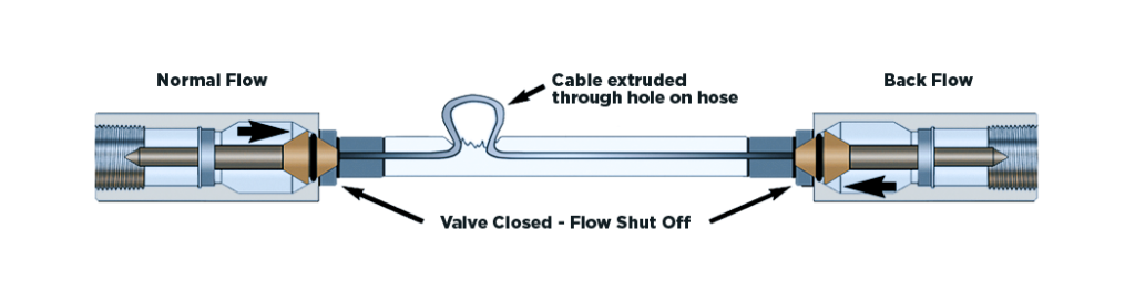
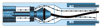
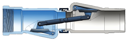
Smart-Hose® Break-Away products use a single, engineered separation ring. This ring has its shear point integrated fully around the diameter so that the bending moment does not rely on the failure of multiple independent elements (bolts) to initiate and accomplish a full, controlled separation. Instead, the ring provides a single element independent of the application. In a pull-away, the forces acting on the joint increase until the ring begins to “tear” at the point on the diameter where the bending moment imparts the highest tension. As the ring begins to fail, the tearing action accelerates around the diameter because the ring is no longer as strong as it was before the failure began. We call this a cascading failure. The real-time trace of this system would demonstrate an initial spike in the force as the hose is stretched taught and then a subsequent and sudden drop-off of the hose tension to zero. SmartHose® Technologies does not recommend repeated straining of a break-away joint area. If a Smart-Hose® Breakaway Hose Assembly is involved in a partial pull-away event, remove from service immediately. Do not reuse.
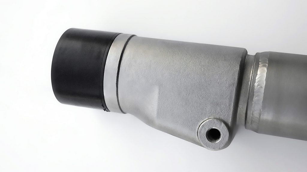
Note: Verified - Metal hose only - 700, 800, P4
Smart-Hose® Technologies Assemblies are not ATEX certified for use in hazardous/explosive environments. Some of the certifications we can support:
- DOT Approvals
- O2 Cleaning Approvals
- CRN - Canadian Registration Number
- CSA - Canadian Standards Association (UL21 hose for LPG SH assemblies
- CEPED - Pressure Equipment Directive (EU)
- NFPA 58 Compliant - Passive Shut Off
- Quality Program - CSA B51 Annex F
The United States Department of Transportation (DOT) and the Pipeline and Hazardous Materials Safety Administration (PHMSA) have jurisdiction for the loading, storage (incidental to transportation,) transporting, and loading/unloading of NH3. To date, no requirements have been released by the DOT or PHMSA citing designated materials to be used for the manufacturing of NH3 delivery hoses.
In general, when a hazard is not specifically addressed in a DOT regulation, Section 4(B)(1) of the OSHA act would apply. A review of the OSHA 29 CFR 1910.111(B)(8) regulations indicates that the hose used in ammonia transfer operations must conform to the joint standard defined by The Fertilizer Institute – Rubber Manufacturers Association (TFI-RMA) standard No. M-5.
Upon examination of the TFI-RMA M-5, Appendix B specifications for Anhydrous Ammonia, metal hose assemblies do not conform to the standard based on the following two (2) notations:
7.4.2 Conditioned Hose Flexing Test: 7.4.2.3 As stated in the TFI-RMA M-5 specification, “The flexing test shall continue for 72 hours at a rate of approximately 470 cycles per hour with a 42-inch vertical movement of a traveling block (72 X 470 =33,840 cycles.)” Corrugated metal hose is made in accordance with NAHAD 400 guidelines and must meet a 10,000 flexing cycle, which is only 1/3 of the number of cycles required to meet the TFI-RMA M-5 specification.
10.0 Markings: As stated in the TFI-RMA specification, “Anhydrous Ammonia Hose assemblies shall be clearly marked at least once every five feet with the manufacturer’s trademark/name, Anhydrous Ammonia, the maximum working pressure in psig, year of manufacture, and TFI-RMA spec” for all hose manufactured after 1.1.1964. Metal hose assemblies do not incorporate markings.
Additionally, practical constraints should also be taken into consideration. The life span of metal vs. rubber in harsh conditions and the inability to completely empty a metal hose of product between deliveries can be of concern. The latter is not a problem for facility hoses that are stored “wet,” however, it could pose a severe hazard for the transport operator who must handle a hose containing residual product.
NOTE: The response is the opinion of Daniel Shelton Managing Partner, HazMat Resources
“Although stainless steel is considered to be an acceptable alloy for use in the NH3 and LPG industries, metal hose assemblies do not meet the regulatory mandates that are specified for the transfer of NH3 and LPG. Federal and State laws prohibit the use of hoses in the transfer of NH3 and LPG services that do not conform to industry standards. The utilization of metal hose assemblies in MC 330/331 transport loading/unloading applications is not compliant with either LPG or NH3 industry regulations (see reference data) and represents an extremely dangerous practice.”
Reference data:
▶ The governing body for the transfer of Liquefied Petroleum Gas (LPG) is The National Fire Protection Association (NFPA). The NFPA Code 58 mandates that all LPG hose assemblies must be manufactured to UL-21 specifications. UL-21 Section 3.1 describes the hose construction as follows: “The tube or lining of a hose shall be made from synthetic rubber of the oil-resistant type.”
▶ 14.1.1 of the UL-21 specifications states: A hose shall withstand 200,000 cycles of repeated bending without breakdown. Again, metal hose is manufactured to NAHAD 400 flexing specifications of 10,000 cycles.
▶ The governing body for the NH3 industry is The Fertilizer Institute – Rubber Manufacturers Association (TFI-RMA) – see Code M-5.
Career Highlights
Daniel Shelton, Managing Partner
HazMat Resources
▶ Extensive experience in the transportation industry, with a concentration on commercial vehicle enforcement, site compliance review, and accident and hazardous material investigation.
▶ Identified design issues with MC 330/ 331 cargo tanks. This led to the Pipeline and Hazardous Material Safety Administration (PHMSA) publishing regulations for the compressed gas industry, HM-225.
▶ Worked with the DOT, EPA, and OSHA to create training materials, workbooks, visual aids, and tools to assure compliance with regulations.
▶ Recognized as an expert in the NH3, LPG, and Hazardous Material transportation industries, and instrumental in defining the regulatory laws associated with each industry.
Life Cycle
It is very difficult to predict a life cycle for any hose assembly because every single end-user has their own particular application and plant conditions that applies to every hose assembly. Some of these variables are:
- Fluid / gas going through the hose assembly.
- Pressure of Fluid / gas.
- Temperature of Fluid / gas.
- Duration of cycle / pulse.
- Number of cycles /pulses per min / hr.
- Environment.
- Hose installation (Straight vs. Radius Bend)
- Unknown Storage Conditions (if applicable)
- Humidity
- Sunlight (if applicable)
- Environmental conditions
- Stacking of hoses (kinks)
- Nearby solvent fumes
To ensure the safety of any operators or personnel in the area during a transfer operation, hose assemblies should be periodically checked for:
- Leaks at the hose fittings or in the hose.
- Damaged, separated or pulled back covers/braids.
- Cracked, damaged, deformed or badly corroded fittings.
- Other signs of significant deterioration such as blisters (if applicable).
- Compromised reinforcement where the wires are exposed and show signs such as unwrapped, broken or corrosion.
- Dents, twists, or kinks.
- Discoloration of color coded hose cover (if applicable).
- Verify test date and pressure are in conformity with requirements for the application.
- Fitting Thread and seat condition.
* In general, the normal expected life cycle for any hose assembly would be approximately 3 – 5 years under ideal conditions.
By design, Smart-Hose Break-Away Hose Assemblies are only offered with the break-away fitting on one side of the hose assembly. While having a breakaway joint on both ends of the hose may initially seem desirable, the redundancy of having breakaway joints at both ends of the hose assembly creates hazard and unpredictability. Our breakaway force values are based off standard installation angles that are supported by numerous hours of testing and refinement. When an additional breakaway joint is added to the equation, the estimated pull force is no longer predictable and the location of the separation is now variable. See the diagram below which outlines the estimated breaking forces based on installation. Also note that horizontal installations, while possible when not avoidable, are not recommended due to the high pull forces.
Smart-Hose Break-Away Hose Assemblies are designed with the intention that the break-away joint will be installed on the facility side of the transfer operation. Facility side installation ensures that the break-away joint is installed in a manner that prevents any undue stress from being applied to the break-away joint. Additionally, having the break-away on the facility side prevents the break-away joint from being dropped and damaged when the hose is being disconnected after the transfer operation is completed. While our product design is robust and dependable for years of service, unnecessary stress and impacts can damage the break-away joint, which ultimately decreases the lifespan of the hose assembly and can cause an unexpected breakaway event.
As with our standard hose assemblies, both end fittings have shut off valves integrated that will shut down in the event of a burst or pull-away.